Convenient barrel manufacturing process (1)
Tianjin Paint Factory Zhang Yusheng
In the manufacturing process of the convenient bucket, only two are different from the ordinary drum, one is the expansion cone, and the other is the top coil. In this part, let's talk about the bulging cone.
Since the unfolded view of the cone is a fan shape, if the plate is cut in a fan shape, the mold is complicated, the damage is large, and the punching equipment is huge, which is not conducive to the mass production of the dragon. Now the expansion cone method is used, and the point is: press the cone when cutting The small diameter of the small head is unfolded, cut into rectangular strips, welded into a cylindrical cylinder by "secondary seam welding", and then inserted into a dilating cone mold in the simplified body, and once expanded on a small hydraulic machine.
This method is only suitable for low carbon steel sheets with an elongation of 20% or more, 08 steel cold rolled sheets, YB364-64 oil drum plates, and YB121-73 tin plate. When cutting, pay attention to the rolling direction of the steel plate so that the stretching direction and the rolling direction are the same, which can prevent cracking and reduce waste.
When the cylinder is welded, if ordinary welding is used, the lap width is 8-10 times of the thickness of the plate, the shear strength at the weld is not a problem, and the fracture phenomenon does not occur here during the stretching. Occasionally, there are cracks in the production practice due to improper use of cooling water during welding, rapid cooling of the metal, thinning of the grain, or the cleaned area of ​​the weld, which is caused by scale or mud. This is an accidental factor and is easy to handle and eliminate.
Due to the precision fixtures, the modern seam welder greatly improves the precision of the weldment. At present, the lap width of the weld is reduced to nearly 1-2 times the thickness of the plate, and the high temperature and high pressure are applied to make the weld close to the butt joint, and the weld is only subjected to tensile stress. Since no cooling liquid is added, the metal is slowly cooled, the crystal grains are coarse, the hardness is low, and the toughness is good, so there is no possibility of breaking when stretching.
1. Principle and calculation of the expansion cone process:
First, the principle:
The cylindrical cylinder is plastically deformed by the internal pressure Po, and the crystal grains of the cylinder metal are elongated and thinned in the circumferential direction, and the stress is maintained at the yield point. The metal deformation does not exceed the fracture limit, and after the external force is removed, permanent deformation is left.
Second, the stress calculation:
It is assumed that the cylindrical body is cut along its axis, and a semi-cylindrical body having a length L is taken as a research object. The pressure acting on the inner surface of the semi-cylinder is Po, and the resultant force N is: (Fig. 1)
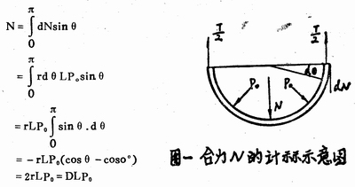
Where r and D should be the average radius and diameter of the cylinder, but the thinness of the plate can be taken as the inner diameter of the cylinder with little error. The balance with the resultant N phase is the internal force T acting on the longitudinal section of the cylinder wall. The value should be:
T=2・S・L・σ ring
Where: S = wall thickness of the cylinder. Obviously, N = T, so D, L, Po = 2, S, L, σ ring
Then: P = 2 · S · σ ring / D
As can be seen from the formula, P. In inverse proportion to D. Obviously, the sigma ring should be taken as the yield limit σS of the material. Σs can be found in the manual according to the nature of the material.
If σ ring = σS is taken, the minimum pressure P required for the bulging cone can be calculated.
Third, the design and calculation of the mold:
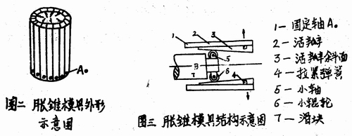
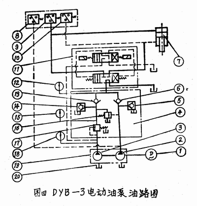
1. Mold construction: (See Figure 2 and Figure 3)
The bulging cone mold is composed of a 16-valve flap, one end of which can be fixed around the fixed axis A. Turn. The 16-valve flap fits into a cylinder with an outer diameter slightly smaller than the inner diameter of the workpiece. The inner diameter of the mold is a cone. When the slider B is pushed forward, when the flap is opened and the cylinder is swollen out of the taper oB, the flap is restored to the original shape by the spring force, and the workpiece is taken out.
The diameter of the bottom of the convenient bucket is D1=270 mm, the diameter of the upper mouth is D2=280 mm, the height is 400 mm, and the material is A. Low carbon steel, its elongation σs>20%, yield strength σs=2000 kg/cm2, taper of the inner cone of the mold is 1/10, divided into 16 flaps, seeking: 1 minimum pressure Po when bulging; 2 slip The minimum thrust F of block B.
P=2·S·σs/D=2×0.05×2000/27=8 (kg/cm)
Where: D takes the bottom diameter D1, S plate thickness is 0.5 mm.
When the outer circle of the mold is divided into 16 lobes, the arc length AB of each lobes is:
AB=πD/16=3.14×27/16=5.3 (cm)
The tension that should be applied to each arc is:
n=AB・L・Po=5.3×40×8=1700 (cm)
Where L is the barrel height.
When the slider is advanced, the axial resistance of each valve is f, then:
f=n・tgα+mfo=1700×0.1+1700×0.15=425 (kg)
Where: α is the slope angle of the flap, tgα = 0.1, and fo is the friction coefficient: take fo = 0.15.
Total thrust F=∑f= 16f = 16×425= 6800 (kg)
3. discuss:
1) The amount of deformation cannot be increased indefinitely, that is, the ratio of the tapered head cannot exceed the elongation σs of the material, otherwise fracture will occur. Therefore, the calculation of the elongation is required:
δ=100%×(D2-D1)/D1≤σs
2), the weld is generally not cracked, because the overlap width is about 4 mm. Welds generally do not need to be checked, and cracks should be found from the seam welding specifications and materials.
3) It is best to use rolling friction between the slider B and the bevel of the flap to prevent wear. At this time, the shear strength check of the small shaft should be performed. In addition, the friction surface should be well heat treated and lubricated.
2. Equipment:
Convenient barrel expansion cone machine currently has three types: hydraulic semi-automatic, hydraulic automatic and mechanical automatic three kinds. China's preliminary trial production has hydraulic semi-automatic machine, hydraulic automatic machine, Japanese multi-purpose mechanical transmission automatic expansion cone hunger, Western Europe, North American multi-purpose hydraulic automatic machine.
The hydraulic transmission semi-automatic and fully automatic expansion cone machine is now introduced.
First, hydraulic machine introduction
1. Oil pump: model DYB-3
It is driven by a two-stage oil pump, namely a high-pressure low-flow swashplate axial piston pump and a low-pressure large-flow gear pump.
In the case of an empty stroke, the high and low pressure oil pumps are simultaneously supplied with oil, and a large no-load speed can be obtained to save labor. When working, the oil is supplied by the high-pressure oil pump, and a large working pressure can be obtained.
It has two oil outlets, the pump is a two-way oil circuit, and the electro-hydraulic reversing valve is used to realize automatic reversing under a given pressure by means of a pressure relay.
Its performance is as follows:
High pressure pump: pressure: 300 kg / cm 2; flow rate: 6 liters / min; plunger diameter: 10 mm; number of plungers: 7, plunger stroke: 8.6 mm.
Low pressure gear pump: model CB-850; pressure: 10 kg / cm 2 ; flow: 50 liters / min
Motor: Model: J02-42-T2; Power: 5.5 kW; Rotation speed: 1430 rev / min; Flow: 200 liters
Valve body part: It consists of high and low pressure check valve, high and low pressure safety valve, sequence valve and power reduction valve.
The high and low pressure check valves prevent high pressure oil and low pressure oil from flowing back to each other after mixing and protection.
The sequence valve keeps the low pressure oil at a constant pressure and draws a control oil pressure from the electrohydraulic directional control valve.
When the pressure is less than 12 kg/cm 2 , the high and low pressure oil pumps simultaneously supply oil to the outside, and a large flow rate can be obtained.
When the pressure is greater than 12 kg/cm 2 , the low pressure oil flows back to the tank through the low pressure relief valve, and only the high pressure oil works.
When the pressure is greater than 20 kg/cm 2 , the high pressure oil tops the power reduction valve, the low pressure oil is returned from the power reduction valve, the low pressure check valve is closed, the power loss is reduced, and the high pressure oil is fully utilized to obtain a large tonnage.
When the pressure is greater than 320 kg/cm 2 , the high pressure oil is returned to the tank through the high pressure safety valve to prevent the oil line from being overloaded.
Working cylinder: diameter: φ125 mm, stroke: 130-200 mm.
Auxiliary cylinder: diameter: φ80 mm, stroke: 400 mm.
2. Semi-automatic hydraulic machine working principle:
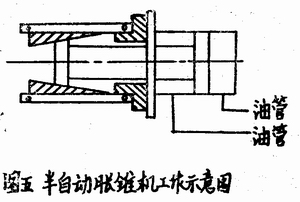
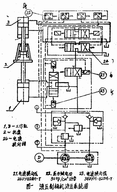
The DYB-3 electric oil pump and the semi-automatic expansion cone oil circuit (as shown in Figure 4) are activated. The working fluid enters the main valve body after inhaling the high and low pressure pumps from the fuel tank. After mixing in the valve body, the electrohydraulic reversing valve is entered. , then enter the working cylinder. Pushing the piston to descend rapidly, the inner cone of the mold pushes the valve to expand outward. After the valve contacts the iron sheet, the resistance increases. The high pressure pump supplies oil separately, the working pressure increases, the simplified body is swollen, and the piston continues to descend to the specified position. Stroke block, resistance increases, working oil pressure rises sharply, pressure relay 9 works, electro-hydraulic commutator 11 works, liquid commutation, piston rises, expansion cone mold shrinks, piston up to the top, oil pressure increases, pressure The relay 10 operates to stop the oil pump from supplying oil and a working stroke is completed.
Description: 1. Motor 2. High pressure piston pump 3. Low pressure gear pump 4. Main valve body 5. High pressure safety valve Pressure check valve 7. Two-way cylinder Safety relay 9. High voltage relay Low voltage relay Electro-hydraulic reversing valve 12. High pressure gauge 13. Low pressure check valve Low pressure safety valve Low pressure gauge 16. Power reduction valve 17. Sequence valve 18. Control pressure gauge 19. Oil pump combination 20. tank
When the semi-automatic expansion cone machine uses the above oil circuit diagram, the working cylinder and the expansion cone mold can be horizontally placed. (Figure 5)
This structure swells one workpiece per working cycle and can produce 400 to 600 workpieces per hour.
3. Automatic expansion cone machine
The automatic expansion cone machine can be used on the entire automatic production line or can be used separately.
Its working principle and oil circuit are basically the same as the above semi-automatic hydraulic expansion cone machine (Fig. 6). Only one feed cylinder 7 is added, and accordingly an electrohydraulic directional control valve 21, as well as a pressure relay 22 and an electrohydraulic directional control valve 23, are added.
The working process is as follows:
The motor starts, the electro-hydraulic reversing valve 23 works, the oil cylinder 1 supplies oil, the piston rises, and the workpiece placed on the tray 2 is pushed into the outside of the expansion cone mold, and the piston is pushed to the predetermined position and then pushed to death, the oil pressure rises, and the pressure relay 221, so that the electro-hydraulic reversal cutting 24 work, the working cylinder 3 into the oil, the piston descends, the expansion cone mold starts working, the workpiece is inflated, the piston is lowered to a fixed position is blocked, the oil pressure rises, the pressure relay works, The electro-hydraulic is reversed, and the two pistons of the upper and lower cylinders are simultaneously retracted, and one working cycle is completed, waiting for the start of the next cycle.
Island Cabinets,Water Sink,Kitchen Island Cabinets,Kitchen Cabinet With Island
Hangzhou Taihua Home Furnishing Technology Co.,Ltd , http://www.taihuafurniture.com