With the continuous development of information technology, mobile phones have gradually become an indispensable tool in modern society. However, once the mobile phone is lost, the information stored in the SIM card is lost, which causes a lot of unnecessary trouble. In order to save these important information, it is very important to make the necessary backups on the computer. This article uses the GPIO port of ST7267 microcontroller to realize the reading and writing of SIM card.
1 hardware circuit design
1.1 ST7267 Microcontroller Overview
The ST7267 has a USB2.O hardware interface, and the mass storage control interface can support various types of NAND Flash. It has 54 KB of ROM and 4 KB of RAM.
1.2 SIM card interface circuit
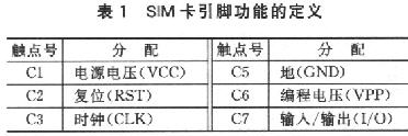
The SIM card pin functions are defined as listed in Table 1.
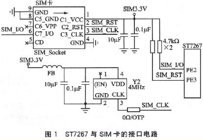
The interface circuit of ST7267 MCU and SIM card is shown as in Fig. 1. The circuit mainly provides a 4MHz, stable clock frequency to the SIM card by the peripheral active crystal Y2. The power supply is output from a LDO by 3.3V, pure DC power to the Cl_VCC of the SIM card. Here, select the PE2 pin of ST7267 as the I/O pin, communicate with the SIM card through a 4.7kΩ pull-up resistor; select the PE3 pin as the reset control pin of the SIM card.
2 low-level software design
The SIM card has a different data transmission method than other memory cards, and it complies with the ISO7816 standard. Therefore, when designing the SIM card, you should pay attention to the width of each data bit during data transmission, and then write the program according to the ISO7816 standard. The first is to receive the correct reset acknowledge signal (ATR), and the second is to send a command to the SIM card to get the correct return data and status flags.
2.1 Calculation of ETU
ETU (basic time unit) is the time for inputting/outputting each bit of data on the SIM card I/O pin. The calculation formula is;
![]()
Among them: parameters F and D are clock frequency conversion factor and baud rate adjustment factor respectively, here the default rate is used, ie F=372, D=1; the used clock frequency f is 4MHz. It can be calculated that the basic time unit is 93 μs.
2.2 Basic data frame structure
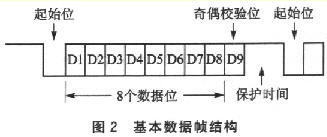
The protocol used for communication is the asynchronous half-duplex character transmission protocol of T=0 as specified in ISO7816-3. The basic data frame consists of 1 start bit (low level), 8 data bits and 1 parity bit, as shown in Figure 2. Among them, the check digit is to evenly check the 8 data bits with itself, that is, the number of 1 must be even. The start bit does not perform a check operation. The SIM card and the microcontroller must be at a high level during the protection time (ie, the I/O port is high). In the T=O protocol, if the SIM card or the microcontroller detects that the parity result is incorrect, the I/O port is pulled low during the guard time to show the error.
2.3 SIM card APDU structure
Application Protocol Data Units (APDUs) include Command APDUs and Answer APDUs. The structure is as follows:
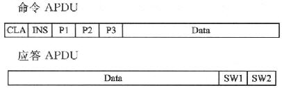
Where: CLA is the type of instruction, A0 is defined as the application of GSM; INS is the instruction code; Pl, P2, P3 are the instruction parameters, P3 indicates the length of the data; Data is the data to be transmitted; SW1 and SW2 are the commands The status returned after processing.
2.4 Design of the basic program module
Let myBit be the storage variable sampled from the I/O port, set Parity to the parity variable, and Parlty to the initialization value of 0. Every time I sample from the I/O port, myBit will perform an exclusive-OR with Parity and the result will be placed in Parity. After sampling 9 times in this way, if the final value of Parity is 0, it means that the parity is correct; if it is not 0, it means that the data reading fails, and an error message is returned, asking the sender to resend.
Office/Meeting charging station is used when staff use most of tablet on meeting and business negotiation with customers. USB port: 10/20 port, that is enough to charge certain devices, full load charging output 5V2.1A, high current voltage precision, low ripple, excellent stability.
Double capacity: the tablets of the operating system, such as tablets / apple iOS / Windows / Chrome, and the smart phones of various operating systems, each equipped with a single LED charging status indicator.
The integrated power supply, USB standard charging port, no wiring, no installation, simply plug the power cord into the socket and start charging. The cabinet is placed vertically, with ABS industrial flame retardant plastic layer. It can manage them on and easy to take them.
Our Storage charging cart can charge and manage for different electronic devices. We can design the suitable storage charging cart according to the size and power parameters of your electronic equipment. Not only can you arrange and store lots of electronic equipment, but also can charge in the same time. Generally there are multiple charging interfaces: 10/20/30/40/52/60/65 units and so on, can be depended on the customer's need to customize and satisfy the different number of charging interfaces, like OEM, ODM. Universal charging solution can be used in any country. All of charging solution have multiple USB port and AC charging interface.

We have intelligent storage sync data charging cart. It can do intelligent disinfection, timing, control switch and synchronous data functions.
This intelligent function can be choose by your inquiry.
1.When electric equipment put in the charging cart, we can choose to disinfection for the equipment. It uses UV sterilizer to kill bacteria. Keep your health.
2.About charging time, you can set up with timer early, as long as press the open switch, the Timer Charging Cart will automatically control and charge your equipment.
3.If you need to transfer data files to charging device, connecting to the data transmission port directly with your computer, and operate synchronous transmission function. This function is only with USB Port Charging Cart.
Public charging station
this product is used for school education, library, hotel, office, factory, meeting room, family, shops, airports, data processing and government work scenario, these places are using a lot of tablets and laptops. Charging stations will work for their collective charge and management. Our products main sold to education place.

Security USB charging cabinet is equipped with LED light to display charging status, red light means charging, green light means full charging or not charging. And we have three point safety locker.
Two with brake casters can make charging cart not move when you put well it on a place.
Our Locker Charging Cart is made of 1.2 mm cold steel sheet material. It is really strong and can understand certain weight. The good quality can be seen.
Our charging cart have safety certification of UL, CE, ROHS,CCC, FCC and REACH, considering the safety and quality assurance. Design two side door to protect power area and curved edge surface to preventing user getting hurt and device. Can be fixed on the wall. Let customer use happy and at ease.

Product certification is complete, safe and reliable, good quality. Looking forward to you cooperation!
Office/Meeting Charging Station
Office Charging Cabinet,Cell Phones Charging Station,Office Charging Station,Meeting Charging Station
Shenzhen Qipeng Maoye Electronic Co.,LTD , https://www.lotcharge.com